Taking a Picture
I recently took a class in PCB design. For my final project, I decided to take a picture with the ESPROS EPC901, which is a 1024x1 pixel CCD image sensor which you can buy in single quantities from DigiKey.
The EPC901 has a tiny and extremely lightweight BGA package.
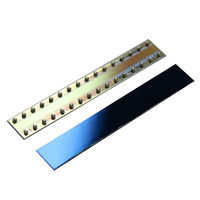
The image sensor is unusual since it has a single column of pixels (as opposed to the image sensor in, say, your cell-phone which has a 2-D matrix of pixels). The aspect ratio of the sensor made me think of strip photography which is a technique where the camera captures a moving object by taking a "video" of a thin vertical slice through a swath of the scene, later reconstructing an image by placing the frames next to each-other.
In fact, you don't need a special camera to create a strip photograph. I produced the following image by taking a video with my cell-phone camera and using a Python script to overlap the video frames such that each frame has been shifted by the speed of the train divided by the frame rate.

There's also a similar technique used in some panoramic cameras where the camera or optic rotates, so that each subsequent "slice" captures a different angle of the scene. I decided to try and capture a picture using this second technique, with the idea that it would be easy to produce a strip photograph by not rotating the optic during the course of the capture.
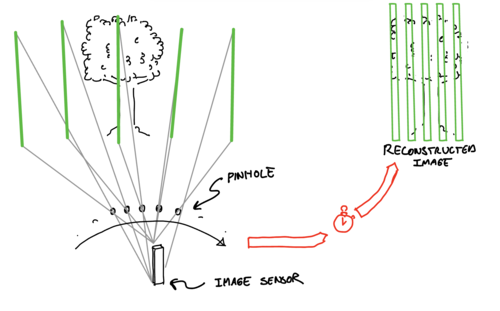
To keep things as simple as possible, I decided to use a pinhole to project the image onto the image sensor. A motor will be used to rotate the image sensor and the pinhole through the scene while the image sensor continuously captures pictures. Once the capture is complete, the individual columns can be concatenated to form the final image.
The sensor and optic rotate through the scene, capturing a series of images which are horizontally concatenated to form the final image.
Hardware Design
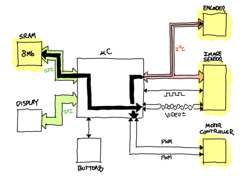
The camera is controlled by a SAMD21G18A microcontroller. During acquisition, the microcontroller's main job is to sample from the image sensor using its internal ADC, and run a control loop to sweep the motor from left to right.
Image Acquisition
The EPC901 can be configured both by pull-up/down resistors and by I2C. I followed the data sheet's recommended settings, but enabled the sensor's differential output since the analog signal must be routed through an unshielded FFC cable to the main sensor board. The microcontroller's ADC can also be configured as a differential input, so there's no additional circuitry required to connect the image sensor and microcontroller.
The main hardware components of the camera.
Most of the inputs to the EPC901 are easy to drive via the SAMD21. There are
lots of pins, but only READ and SHUTTER are actually required to start and
read-out an image. The SHUTTER pin is held high for the desired duration of
the exposure, and then the READ pin is used as a kind of clock to shift out
the 1024 samples one-by-one.
Each time the READ signal is pulsed, the EPC901 puts a voltage differential
on the output which corresponds to the next pixel's illumination level. This
voltage is sampled by the microcontroller, and the READ signal is pulsed
again once the ADC reading is complete. This process is completed 1024 times,
one for each pixel in the column.
The time to read an image is limited by the microcontroller's ADC, which can sample at a maximum of around 500k samples per second. This turned out to be a significant issue – the slower images are captured, the slower the motor has to move in order to capture a wide swath of the scene.
The image sensor is attached to a daughter board by FFC cable so that it can rotate during image acquisition. (A pinhole and additional light-blocking tinfoil covers the sensor during normal operation.)
The microcontroller is also limited by its onboard RAM. A monochrome 1024x1024 image with 8 bits per pixel is 1 MiB – already too much to statically allocate in the SAMD21's memory. Further, the camera is designed to capture panoramic images, so I expected to have to store images which are 2, 3, or 4 MiB. To satisfy this requirement, the microcontroller is connected to an 8 MiB pseudo DRAM via SPI. The SAMD21's DMA subsystem is used to pipe ADC samples directly into this external memory.
Motor Control
A tiny DRV8210 is used to drive the sensor board through a half-rotation during image acquisition. A magnetic encoder is attached along the rotation axis of the image sensor, providing the microcontroller with the angle of the sensor. The encoder is configured by I2C, but is read by measuring the duty cycle of a PWM signal that the encoder generates. The motor controller is commanded by two PWM signals generated by the SAMD21.
User Interface
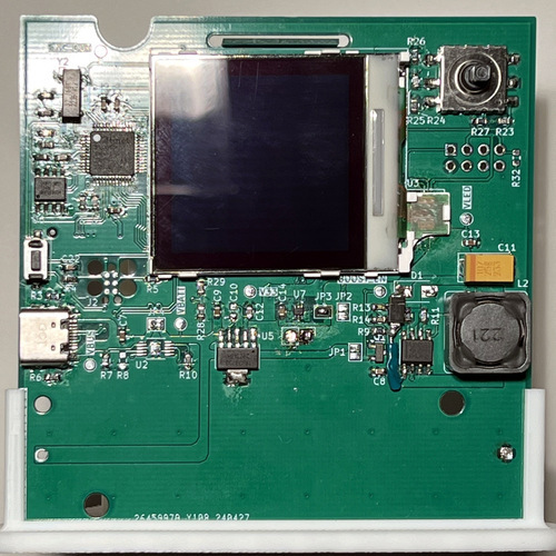
The (primitive) user interface of the camera is implemented by a Nokia 6100 color LCD and a 5-axis button pad. The color LCD requires a 7 volt power rail to supply the LED backlight which is generated by a boost converter circuit on the main PCB.
The 5-way button pad is used to adjust the camera's exposure duration and to trigger a capture.
The main board of the camera with LCD at center and the 5-axis button pad on the upper right.
Software Design
The firmware for the camera is written in C++ using the PlatformIO framework. The main challenges in the design of the camera's software were the management of the SAMD21s shared resources, and the management of concurrent tasks. During acquisition, it's necessary to run a control loop and simultaneously sample from the ADC. These tasks involve capturing PWM from the encoder, commanding the motor using PWM timers, sampling from the ADC to get pixel data, and writing that data to the SRAM. The ADC acquisition should happen as fast as possible to minimize rolling shutter and to allow the motor to run at a reasonable RPM.
In order to achieve the highest sample rate of the ADC while also allowing
some CPU cycles to run the motor controller, it was necessary to use the
SAMD21's DMA and event systems. The DMA allows the ADC to write directly to
the external SRAM, and the event system allows the microcontroller to
automatically generate a pulse on the READ line when the ADC is done reading
a sample. This allows the CPU to intervene only after sampling an entire
column of the image (about once every 2 ms sampling at 500kHz), rather than
on every pixel (which would require intervention every 2 us).
The motor control loop cannot benefit from quite as much autonomy, but the SAMD21 allows for PWM capture to occur entirely in hardware, so CPU cycles can be saved just for updating the state of the PID controller.
Other subsystems require shared access to the ADC. The 5-way button, for example, uses a voltage divider network to generate unique voltages for each of the 5 possible directions which are sampled by the microcontroller's ADC.1 A simple mutex is used to prevent the button subsystem from sampling from the ADC while an acquisition is taking place.
The button subsystem, motor controller, encoder, image sensor, display, and status LED all need time on the CPU, but the amount of time varies significantly from subsystem to subsystem. For example, the status LED only needs to update once every 100 ms or so, while the motor controller's control loop needs to run at a relatively high frequency, and the button pad needs to be sampled often in order to make the input feel responsive. In order to accommodate these timing requirements, each subsystem gets a class implementing the interface defined below:
template <typename M>
class AbstractTask
{
    friend class Scheduler<M>;

public:
    virtual YieldAction do_work() = 0;
    virtual const char *name() = 0;

    int deadline() { return m_deadline; }
    bool has_messages();
    bool get_message(M *m);

private:
    TaskState m_state{TaskState::DEAD};
    // The time at which this task should resume work on the CPU.
    unsigned long m_deadline{0};
    MessageQueue<M> m_message_queue;
};
Where YieldAction is defined as:
struct YieldAction
{
    enum Type
    {
        WAKE_AFTER_DURATION,
        WAKE_ON_MESSAGE,
        DIE
    } type;
    int duration{0};
};
A task does work by overriding do_work, which is a function that usually
handles any messages in the queue, and does a little bit of work (for example,
running one iteration of the PID loop, in the case of the motor controller
task). It returns an action which the scheduler should take after the work is
done (see YieldAction). The scheduler is implemented as a priority queue
where the keys are the m_deadline of each task. The scheduler has no
priorities, and so starvation is not possible (so long as one of the tasks
doesn't loop inside do_work).
Results
The below is the most successful image I acquired with the line camera:
An image through a four-pane window, looking onto the roof of another building with a large tree next to a smaller, more distant tree in the background.
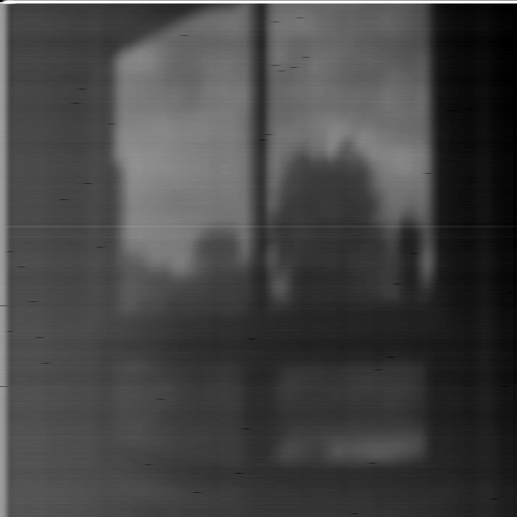
The image has several flaws, the most noticeable of which are probably the random black pixels. I believe these are due to SRAM write errors caused by poor adherence to the chip's timing requirements, or some issue with the DMA transfer. Even though the image is pixelated and has low contrast, we can also see that the optical system (a pin-hole poked through a sheet of aluminum foil) has trouble reproducing small details. A smaller hole, further from the image sensor would probably increase the detail.
The main issue with the image (in my opinion), however, is that it's not a panorama. In fact, the above image is just a thin vertical slice of the camera's output, which I've stretched to fill a square window. 2 I was never able to capture a proper panorama with this camera because of a mechanical issue with the motor.
The Motor Issue
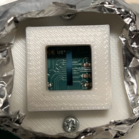
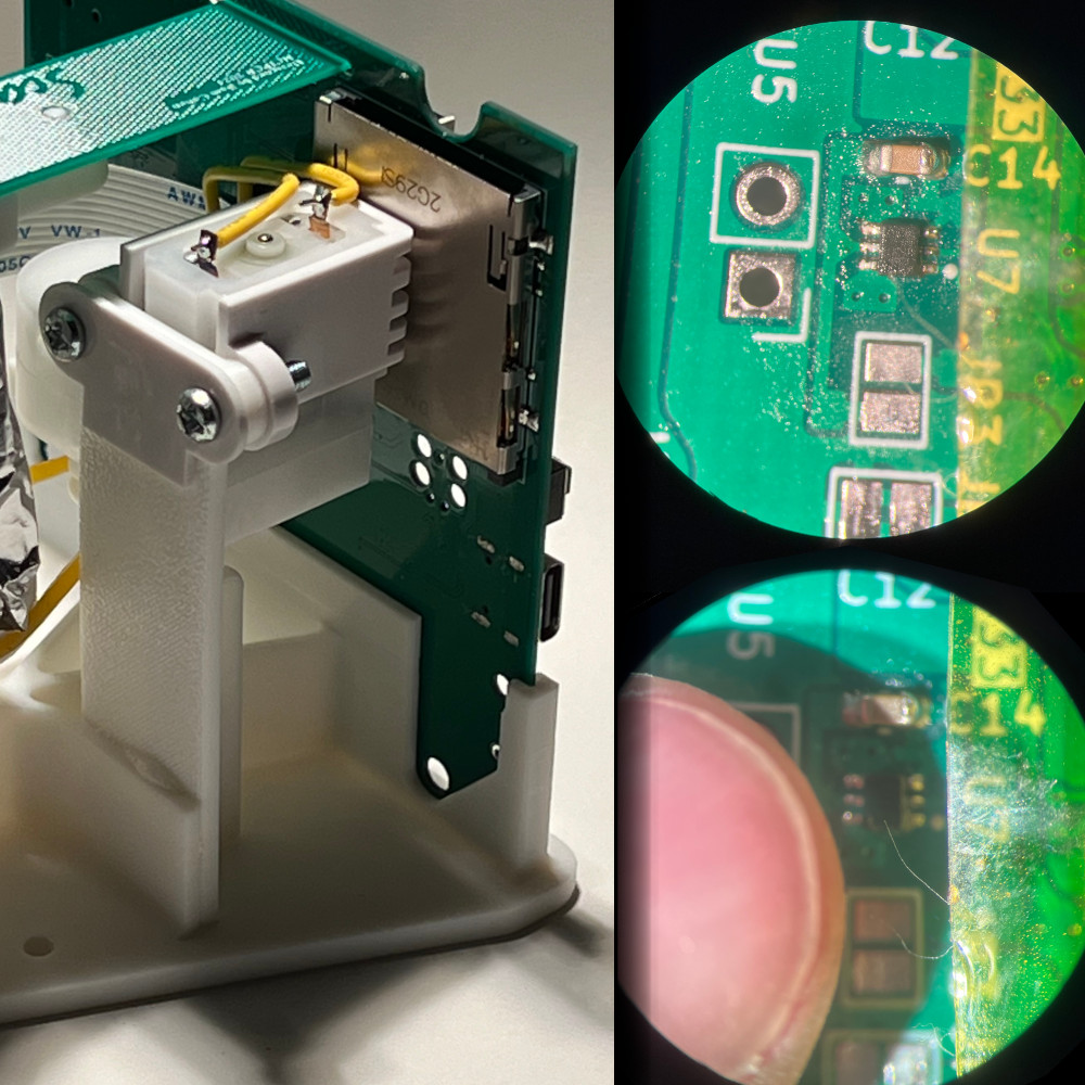
On the left, the camera after a larger motor had been added. Compare right, the motor controller under a microscope, and with my thumb.
 In order to capture a frame, the image sensor needs to sweep across the
scene. To do this, the camera uses a motor which spins the sensor on its
axis. The duration of this spin needs to be slow enough that the image
sensor has time to capture sufficient frames to form a complete image. If the
motor is too fast, the angular resolution will be small because not enough
frames were captured for every degree of motion. If the motor is too slow, we
won't capture a wide angle, but we'll have high angular resolution.
In order to capture a frame, the image sensor needs to sweep across the
scene. To do this, the camera uses a motor which spins the sensor on its
axis. The duration of this spin needs to be slow enough that the image
sensor has time to capture sufficient frames to form a complete image. If the
motor is too fast, the angular resolution will be small because not enough
frames were captured for every degree of motion. If the motor is too slow, we
won't capture a wide angle, but we'll have high angular resolution.
I used a tiny geared DC motor to spin the sensor. This tiny motor wasn't geared down as much as was probably necessary, and so the image sensor made a speedy sweep across the scene during each acquisition. Sampling as fast as possible, it was not possible to capture more than a fraction of the scene.
To remedy this, I attached a much larger geared motor (with a bigger gear reduction) to the sensor, and additionally fixed a belt to further increase the torque (and reduce the speed) at the pivot of the sensor. The thought is that a sufficiently slow moving sensor will always allow a full acquisition, even at a very slow sample rate, at the expense of the acquisition taking longer. This gear motor, which I found at the bottom of a cardboard box of miscellaneous electronics bits, drew a surge of current from the minuscule motor controller, probably causing a voltage spike which blasted the innards of the microcontroller, turning the prototype into a space heater.
I wasn't able to take any more pictures with the camera after this experiment.
Improvements for Version 2
If I were to build a second version of the scanning line camera, I would first and foremost address both sides of the The Motor Issue:
- The motor issue could be solved by sampling faster. The SAMD21 is a little under-powered for the task of sampling from the EPC901. A better design might include a stand-alone ADC with faster sample rate, and a microcontroller which can handle the increased data rate. Of course, there is a limit to how much faster we can sample, because we still need to allow time to expose the image sensor on each frame.
- The motor issue could also be solved by choosing a more appropriate motor, or by doing away the motor altogether. One attractive solution is to use a purely mechanical system – probably involving a spring and a damper – to rotate the sensor, and potentially an encoder to compensate for any nonlinearities in the motion. The motor and its controller are the most power hungry components of the system, and big contributors to noise, and so removing them would certainly benefit other electronics which aren't directly related to sensor motion control.
Secondly, the user interface could be somewhat improved. Mainly, I'm referring to the old Nokia 6100 display which I recycled to use on this project. There are very cheap displays to be found with better color rendering, and without the need to generate 7 volts for the backlight.